The outlook for verification is as follows:
Acquisition of Thermal Radiation Technology
Acquisition of Air Conditioner (Convective Heat Transfer) Technology
Thermal radiation effect due to temperature difference generated by transporting heat to the ceiling with an air conditioner
Consideration of the influence of the hierarchical relationship between radiant temperature from the ceiling and room temperature on sensible temperature
Generally, radiant cooling is set as Room Temp 26℃ > Wall Temp 23℃, and radiant heating as Room Temp 18℃ < Wall Temp 25℃, but mathematically the sensible temperature becomes the same. How does it feel if radiant cooling is Room Temp 23℃ < Wall Temp 26℃, and radiant heating is Room Temp 25℃ > Wall Temp 18℃?
Observation of performance of primitive model of Cooling/Heating Pod
Measurement of insulation performance and heat capacity of current log house
High insulation of current log house
Confirmation of heat capacity required for heat storage tank
Convective heat transfer (air conditioner) control: time until effect appears after trigger and ΔT potential
 Control by heat dissipation change and suppression control by reverse heat quantity
Thermal radiation (wall temperature) control: time until effect appears after trigger and ΔT potential
 Control by heat dissipation change and suppression control by reverse heat quantity
Creation of Cooling/Heating Pod prototype, Evaluation of convective heat transfer and thermal radiation performance
Algorithm to control sensible temperature: Outside temp, Room temp, Wall temp, Request from resident
Examination of mechanism to deliver necessary heat from heat source to multiple pods
2025.9.5 Realizing Cold Radiation with Radiant Panel Prototype
I wanted to realize warm radiation from a large area, so I disassembled an electric carpet operating at high temperature or a heating panel made in Europe and operated the resistor at low voltage. Even at about 5W, I had the realization that I felt a warm sensation at a distance of 1m if it was radiation from a large area.
However, there was no good way for cold radiation from a large area, and an ice pillow was too small in area to get a realization.
I wanted one radiant panel... but radiant panel manufacturers are all engineering-type companies, so they are unlikely to share it with an amateur easily.
So I made a quick self-made one by adhering and fixing 10 square pipes of 1m to an aluminum plate of H995 T500 T2mm, painting the front matte, and insulating the back.
That black panel in the back is it.
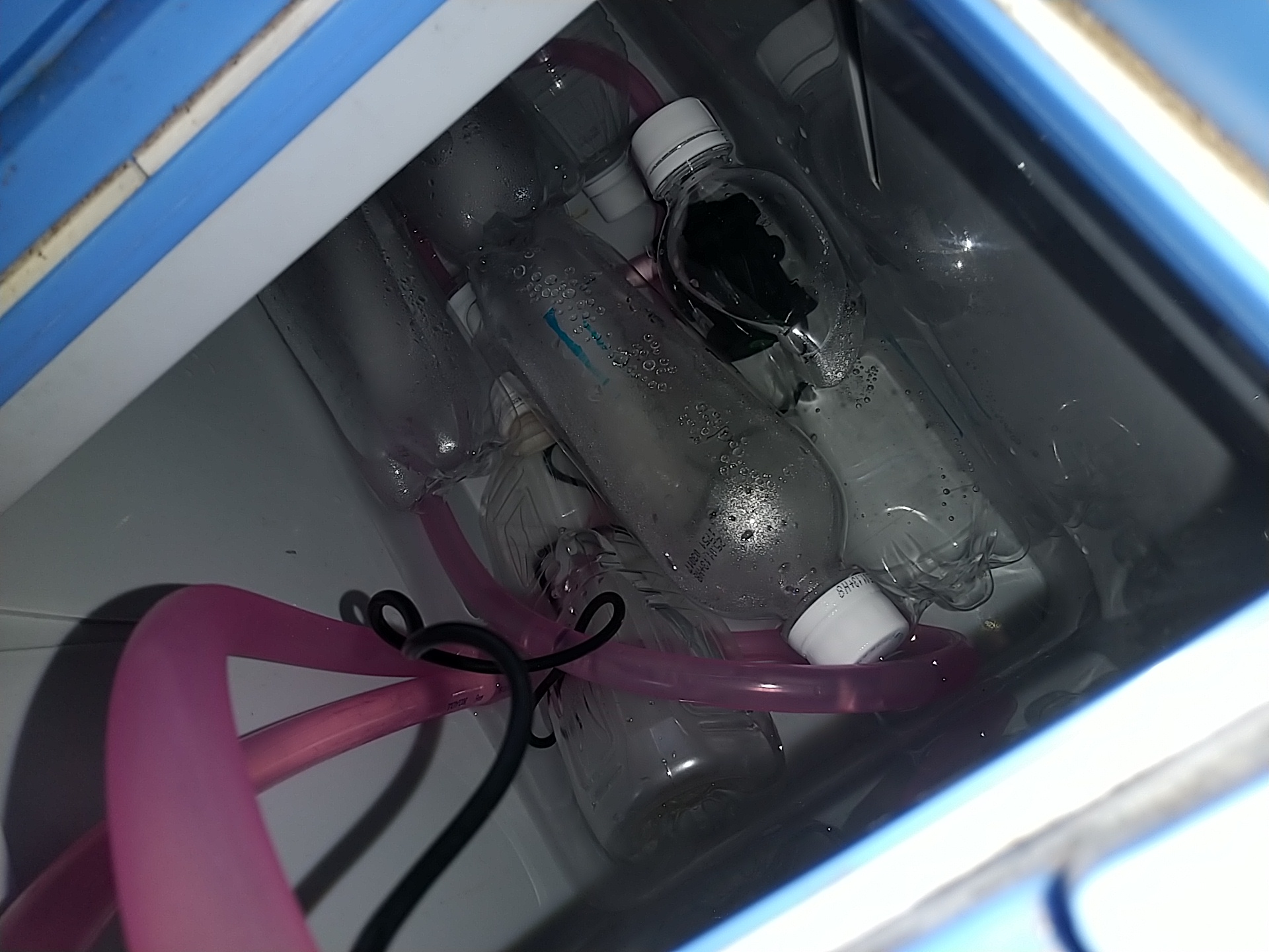
I tried pouring ice water made in a cooler box into that panel with a pumping pump. First, I was worried whether the radiant panel would conduct the temperature of ice water to the panel surface well, but the temperature of ice water seems to be reflected on the panel surface temperature without delay. Also, I measured the temperature from end to end with a radiation thermometer, and there seems to be no large temperature unevenness.
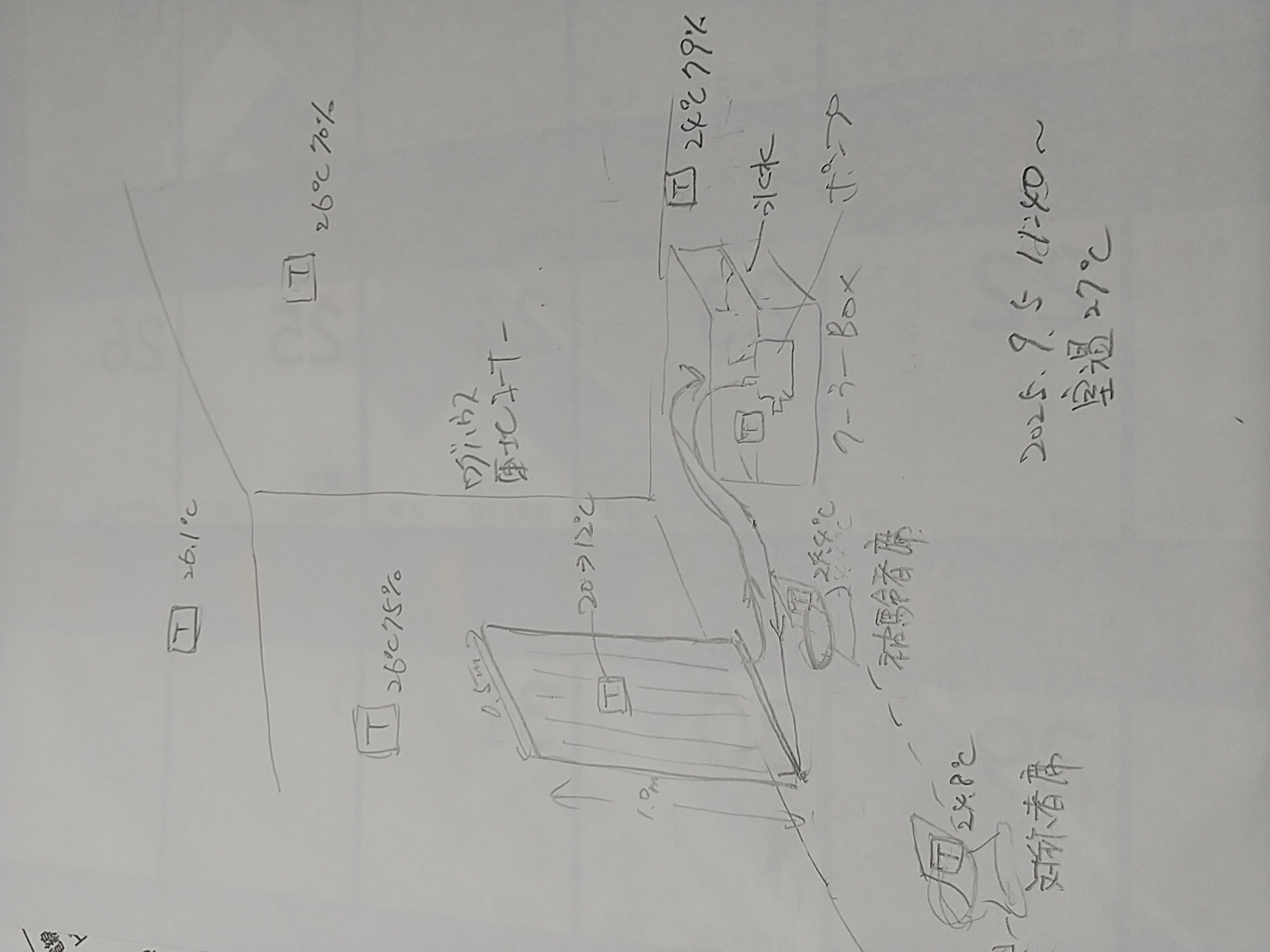
So I set up a subject seat at a distance of 0.5m in front of the panel and a control seat about 1.5m to the left of it, and sat alternately. As a result, I certainly felt a cooling sensation, albeit vaguely, in the subject seat.
When observing at a fixed point with a radiation thermometer, the backrest of the subject seat was 0.4℃ lower than the control seat. By the way, the temperature of both backrests was equal before the experiment, so I was convinced that cold radiation was certainly occurring.

I noticed one thing so I will record it.
There was originally about 5kg of water in the cooler box, and I put 6 frozen 500ml PET bottles continuously into it and made cold water with the heat absorption (46Wh/bottle) when they dissolved.
I thought it would last 3-4 hours because the cooling of water was estimated at about 88Wh and the radiation of the panel at about 50Wh/h, but it melted completely in about 2 hours.
I suspected that condensation took the cold heat, but since the amount is known, it would be an influence of several Wh/h.
Suddenly my feet were cool, so when I measured it, the floor which should originally be 24℃ same as room temperature had dropped to 20℃ at the foot of the panel.
This is not due to radiation but heat transfer by natural convection, and if estimated at 30Wh/h, the calculation roughly matches.
An obvious realization that when radiating panel, heat is always taken away by convection as well.
The heating effect of the radiant panel seems to be more clearly perceivable, so I want to try it, but the spot cooler in the log house cannot lower the room temperature of the log house, which (should have) intense heat transmission, to 18℃. So I definitely want to experience it when the season comes when the temperature drops below 18℃.

...So that's it for this case.

2025.9.5 Estimating Wide Range of Convective Heat Transfer Coefficient
I want to know how much wide range can be expected for the air conditioner function of Cooling/Heating Pod.
Because the air conditioner function of Cooling/Heating Pod requires strength adjustment, or there are times when you want to air-condition with all your might even when the heat source weakens and approaches room temperature.
In any case, adjusting air conditioning with the residual heat amount of the heat source that decreases moment by moment (that is, the temperature of the heat source cannot be controlled) is basically based on the flow velocity of the blown air.
The heat transfer coefficient to the air blown from the heat source seems to be generally expressed by the following formula.
Transfer coefficient = Heat transfer coefficient of natural convection × √(Wind speed / L)
Here, L is the representative length, and its meaning is a numerical value that characterizes the phenomenon currently occurring, so what it is depends on the time and case.
So the theme of this experiment is to roughly estimate what is the representative length in the structure of the air conditioning function of Cooling/Heating Pot.

The experiment starts around 14:30. Place 3 frozen 500ml PET bottles horizontally at intervals of 30cm in an environment with floor temperature of about 25℃, set the flow velocity of air flowing in the vertical direction, and investigate the time when each ice melts completely.
Then, the reciprocal of the time required for complete melting should be the ratio of convective heat transfer coefficient.
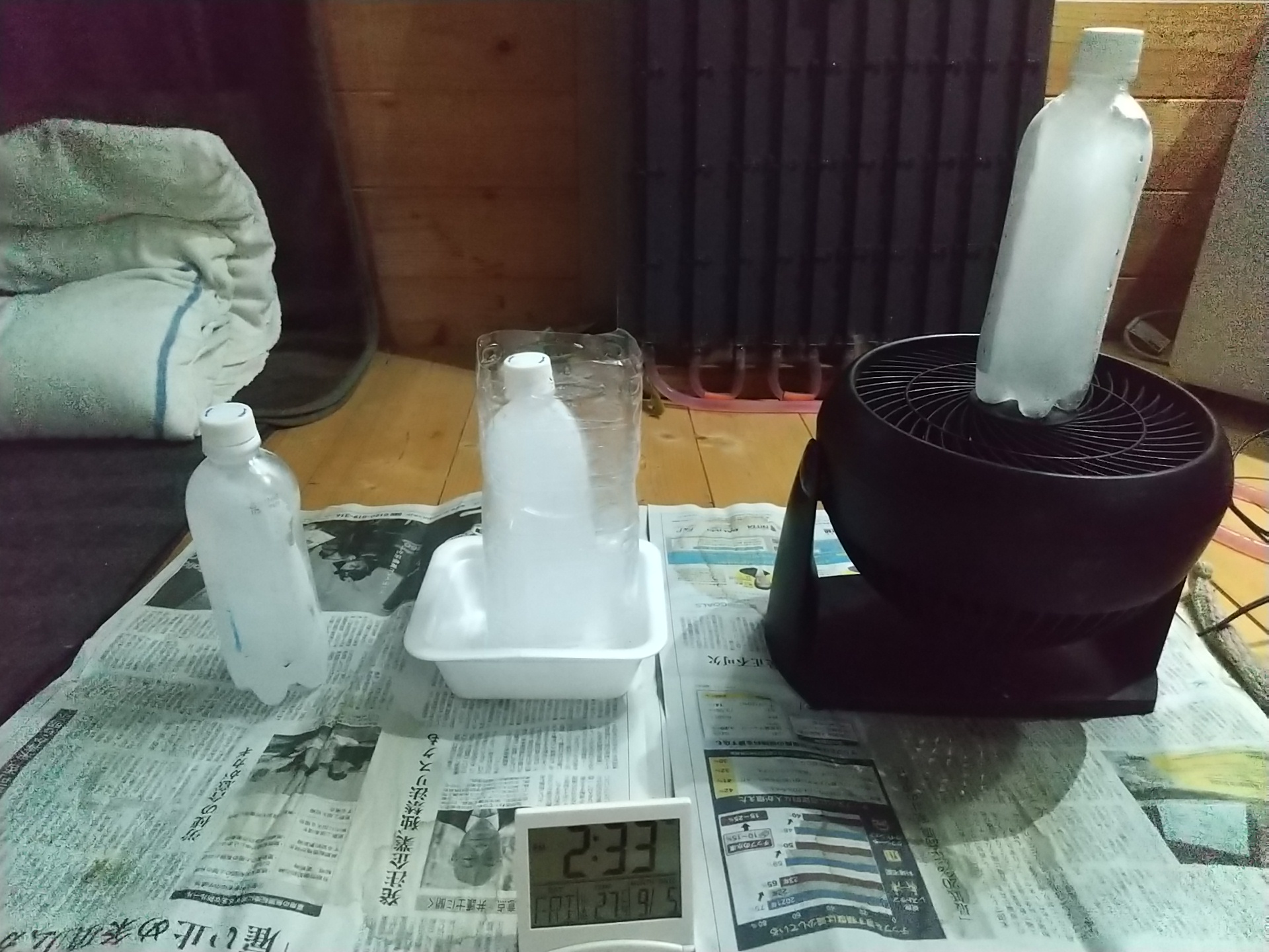
Leftmost is natural convection. Middle is convection prevention. Right is forced convection of 3.5m/s with a circulator.
The results are as follows:
14:30 Defrosting start
15:29 Right PET completely defrosted
18:40 Left PET completely defrosted
At that stage, the middle PET was about 50% defrosted.
In other words, it is estimated that complete defrosting of forced convection 3.5m/s takes 1 hour, natural convection takes 4 hours, and convection prevention takes about 8 hours.
Applying them to the above formula, L = 0.2m was obtained.
Beforehand, I imagined that the representative length was either the PET diameter 0.065m or the height 0.2m, but since 0.2m matched perfectly, I tentatively decided that the representative length L is the height of the wind tunnel of Cooling/Heating Pod.
With this, the wide range of air conditioner capacity of Cooling/Heating Pod can be estimated as a function of wind tunnel height and flow velocity.
Note that for the 8 hours of convection prevention, it is thought that heat conductivity of the outer shell PET etc. is also effective besides overflow convection from the opening, so valid estimation cannot be made, but keep it as knowledge that if the air conditioner fan of Cooling/Heating Pod is stopped to prevent convection in the wind tunnel, heat transfer can be suppressed to about half of natural convection.

2025.10.3 Experiment if ceiling can be cooled/heated by air conditioner function of Cooling/Heating Pod
Since installing radiant panels on the ceiling for radiant cooling/heating is various difficult, it would be good if the cooling/heating temperature could be transported from Cooling/Heating Pod to the ceiling with a circulator. I tried an experiment to know feasibility thinking so.
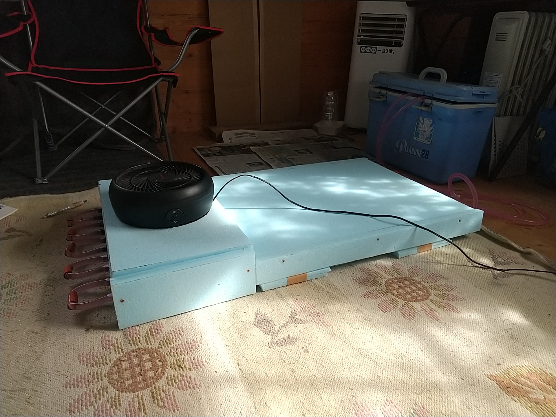
First, the circulator to transport temperature to the ceiling was composed of a wind tunnel that transports air along the radiant panel prototype and a circulator that transports the air in the wind tunnel to the ceiling.
The radiant panel prototype is incorporated into a wind tunnel made of Styrofoam, and when the sucked air moves along the radiant surface, it is cooled, pooled once before the circulator, and then an upward airflow of about 1m/s is sent.
Originally I wanted a wind of about 3m/s, but the air resistance of the wind tunnel is quite large. Can't be helped.

Previously, I pasted insulation foam 30mm thick on the ceiling.
I set a grid of 0.5m intervals on the ceiling and observed the temperature change at a fixed point. The control point was the temperature beyond a crosspiece of about 10cm height. Because the airflow hitting the ceiling should flow along the ceiling but descend before the crosspiece.
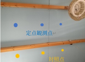
The result felt like this a few minutes after the start of sending:
With an injection airflow about 5℃ lower than room temperature, the ceiling changes by Δ-1℃.
With an injection airflow about 3℃ higher than room temperature, the ceiling changes by Δ0.5℃.
The expression is vague because the ceiling temperature changes moment by moment and I am not confident about temperature measurement, and there is a sign that the airflow is also wrapping around the comparison point beyond the crosspiece.
Since accuracy is unlikely to improve even if I do this any longer:
Ceiling surface temperature (with small heat capacity) seems controllable by airflow from Cooling/Heating Pod.
But a considerable amount of heat seems to be taken away between Cooling/Heating Pod and the ceiling.
I'll stop at this realization. After converting the log house to UA value 0.3W/(m2・K), I will observe in detail together with the movement of airflow.
2025.10.22 Estimate UA Value of Current Log House
When the prototype of Cooling/Heating Pod is completed, I want to evaluate its performance in the log house converted to UA value 0.3W/(m2・K).
The reason is that the evaluation of Cooling/Heating Pod prototype needs to be performed in a room with the outer skin heat transmission performance UA value 0.3W/(m2・K), which is the target this time.
Does the heat storage tank part of the prototype have the "heat capacity" necessary to control room temperature for 24H? Does the heat exchange part of the prototype have the "heat transfer speed" capable of controlling room temperature sufficiently fast? Can the ceiling surface temperature be controlled by the airflow from the prototype?
Proper evaluation cannot be done in the current log house with intense (supposedly) heat transmission...
Prior to that, when I estimated the UA value of the current log house with intense (supposedly) heat transmission by performing a simple heat transmission experiment, it was 1.4W/(m2・K)... It was more excellent than I thought (I will omit the experiment content because it is not the main subject).
On the experiment day in midwinter, I usually leave home around midnight and arrive at the log house in the middle of the night, but since Room Temp = Air Temp and it is freezing cold, I thought a larger amount of heat was transmitting.
To bring it from 1.4W/(m2・K) to 0.3W/(m2・K), roughly speaking, it is work to paste about 110 sheets of 40mm thick insulation foam without gaps inside the outer skin area 72m2 of the log house, which is quite tough.
Of course, window 8m2 will be pasted in a form that completely blocks it. I don't want the floor to be boggy, so I paste it from the outside on the floor.
It feels bad that the window is blocked, so I make it so that the insulation foam can be removed only for the window part except during the experiment. I will finish this work by the end of the year boldly.
Another unexpected thing was that the heat capacity of the log house was quite large. Even after turning off the 1kW Delonghi which is the heat source after the heat transmission experiment, the inner wall temperature did not drop easily.
When calculating the heat capacity rate of pine wood 44mm thick x 72m2 again, it is about 3500KJ/K, so that's natural. I was happy to become able to understand the actual situation little by little by calculation.
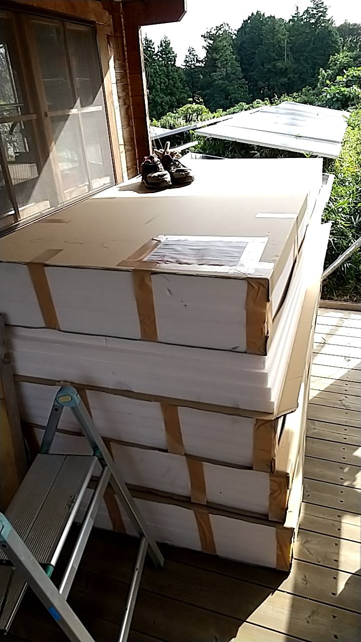
Since all inner walls become insulation foam, I avoided generally sold blue Styrofoam and adopted Kanelite of the same specification. I searched around and purchased 24 sheets for the first order at Nafco and put them on the balcony, but I am overwhelmed by their presence.
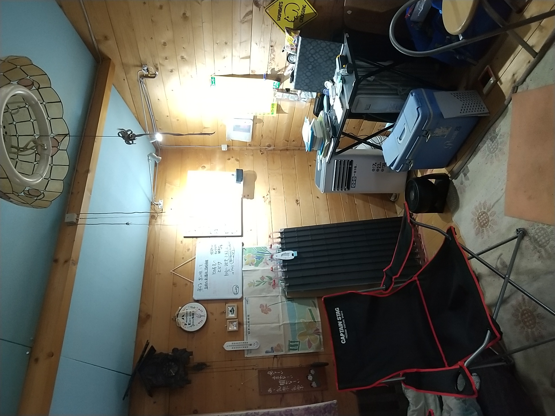
Quite a variety of household goods have been brought into the log house built by DIY 3 years ago, and to paste Kanelite on the wall, it is necessary to evacuate those household goods somewhere once, which is troublesome... I am hesitating.
2025.10.23 Is Cooling/Heating of High Insulation Housing Possible with Compact Cooling/Heating Pod?
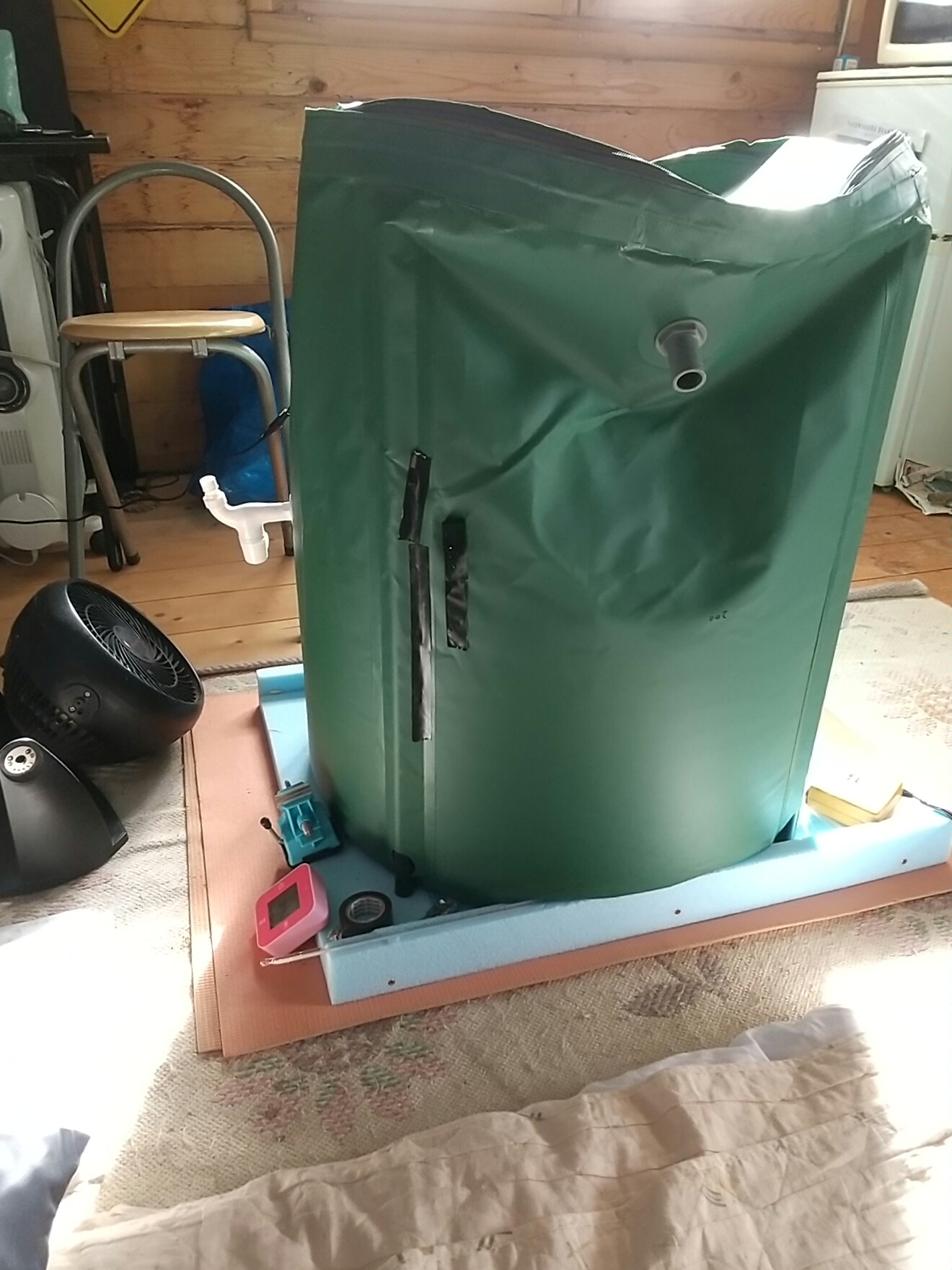
If air conditioning and radiant cooling/heating can be performed with a heat storage tank of about 100kg, I think it can be said to be a "compact Cooling/Heating Pod that fits into the interior of the living room".
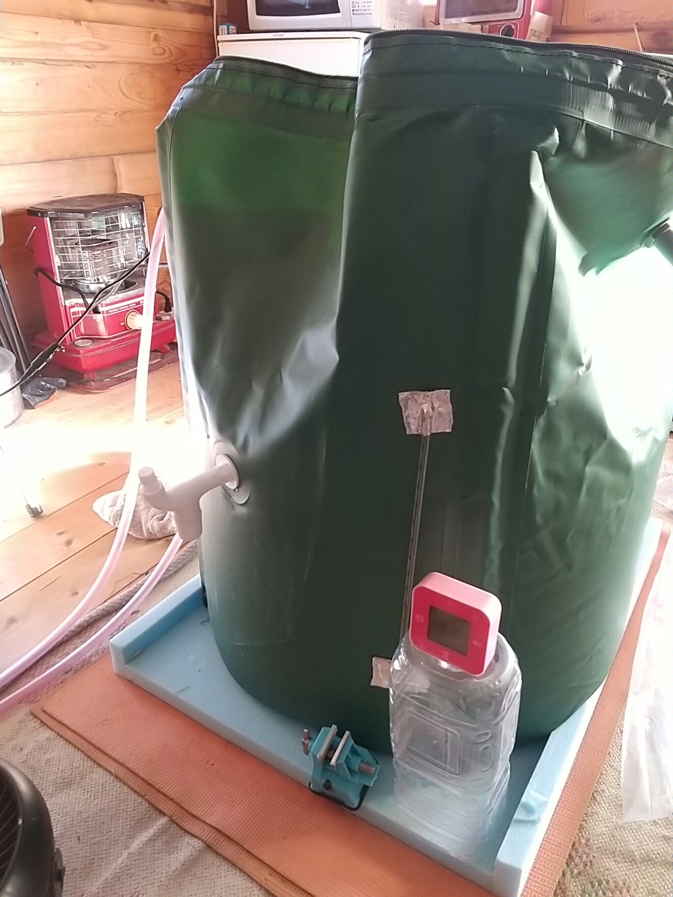
To foresee the possibility, put 100kg of water in a water tank with volume 1m3 and surface area 1m2, place it in the center of a log house with room temperature 20℃ (UA value 1.4W/(m2・K).
We experimented whether room temperature of 18℃ can be maintained for 6 hours with the "heat capacity" obtained when heated to 50℃ and the "heat transfer speed" while the water tank cools down moment by moment thereafter.
We thought that if that goes well, in a living room with UA value 0.3W/(m2・K), maintenance of room temperature of 18℃ for 24 hours, which is 4 times 6 hours, can be expected.
We started heating with an 870W electric heater from 15:00, turned off the heater when heated from 14→51℃ in about 6 hours, and observed the state of heat dissipation.
When estimating the magnitude of convective transfer during heating, it seemed to be less than 30W, so I thought that room temperature could not be maintained by natural convection and it would not be an experiment, so I hurriedly blew a circulator on the side to increase the convective heat transfer coefficient.
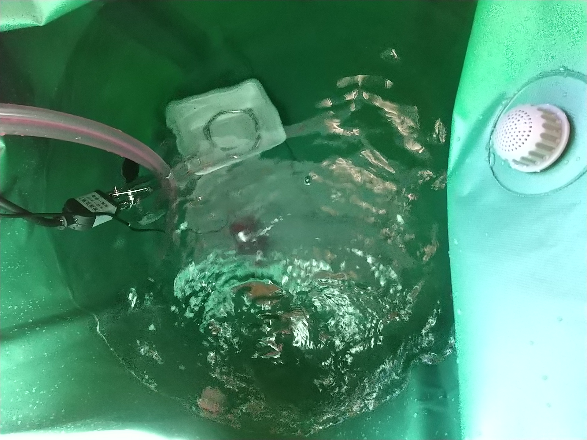
Also, the water tank was agitated by a pump so that it would not become a temperature layer.
Note that the outside temperature was almost constant at 10℃ during heat dissipation.
Result: During heating, total heat from electric heater was 5.16kWh, while heat obtained by water tank was 15,540kJ=4.32kWh, so 0.84kWh was dissipated.
Next, regarding the state of heat dissipation for 1.5 hours from 21:00: The heat lost by the water tank with intermediate value 44℃ was 0.544kWh/h. Subtracting estimated thermal radiation 0.117kWh/h from that, 0.427kWh/h is estimated to be convective transfer.
Heat dissipation for 2 hours from 23:00: The heat lost by the water tank with intermediate value 36℃ was 0.467kWh/h. Subtracting thermal radiation 0.103kWh/h from that becomes 0.303kWh/h convective transfer.
For 8 hours from 21:00 to 4:00 the next day after storing heat capacity in the wall, room temperature 18℃ was maintained, so it seems that heat transmission 0.605kWh/h from Wall Temp 16℃ → Outside Temp 10℃ was covered by heat capacity of log material and convective transfer and thermal radiation of water tank.
Then, if the log house becomes high insulation of UA value 0.3W/(m2・K), heat transmission becomes 0.129kWh/h, so with 100kg water tank and outside temperature 10℃, room temperature 18℃ can be maintained for 38 hours.
Even if outside temperature is 5℃, it can be maintained for 24 hours by calculation. Actually, daytime outside temperature is slightly higher than minimum outside temperature, so it becomes a margin of maintenance time, but reheating may be necessary on the way in the bitter cold season.
The prospect stands... so stop babbling and proceed with high insulation of the log house.
January 30, 2026: Log house insulation completed
80mm thick Kanelite was applied to the inside of the ceiling and side walls, and 80mm thick Kanelite was applied to the outside of the floor as much as possible, sealing any gaps. 4mm of transparent polycarbonate hollow board was added to the double-glazed windows, but heat leaked out, so 40mm of removable Kanelite was installed to insulate the house only during experiments. The UA value measured at midnight, when the log house reached thermal equilibrium and the effect of the structure's heat capacity was minimal, appears to be around 0.5 W/(m2・K).
We will initially conduct basic experiments on the heating and cooling pod at this level.
February 9, 2026: Controlling the radiant temperature of the ceiling, side walls, and floor with an air conditioner
We want to control the radiant temperature of the structure by sending a gentle breeze at a certain temperature from a heating/cooling pod installed in the center of the floor to the surrounding structure (ceiling, side walls, and floor) through heat exchange between the breeze and the structure. This would be much easier than using radiant panels.
It is quite difficult to deliver warm or cool air to a desired location with minimal heat loss. For example, a gentle breeze warmer than room temperature will drift above the desired location due to buoyancy. Furthermore, if not properly directed, it may disappear due to heat exchange with the surrounding air along its path. The same is true for a cool breeze.
Therefore, we want to constantly change the temperature, direction, and speed of the breeze to minimize the effects of buoyancy on the temperature distribution in a living room and minimize heat loss along the path of the airflow.
We will devise and demonstrate this control method.